Friday, 31 January 2025


 SketchUp in Mechanical Engineering

SketchUp is a powerful 3D modeling software widely used in mechanical engineering for designing and prototyping mechanical components, assemblies, and systems. It offers an intuitive and user-friendly interface, making it a popular choice among engineers and designers for developing detailed mechanical structures. One of the key advantages of SketchUp is its ability to create precise and scalable 3D models, which help engineers visualize and refine their designs before moving to the manufacturing stage. With its extensive library of pre-built components and plugins, SketchUp streamlines the design process and enhances productivity in mechanical engineering projects.

In mechanical engineering, SketchUp is primarily used for conceptual design, rapid prototyping, and visualization of mechanical parts. Engineers can create 3D models of machine components, including gears, shafts, bearings, and assemblies, to analyze their fit and functionality. The software also allows for the integration of various mechanical elements, enabling engineers to simulate the interactions between different parts and assess their feasibility. By using SketchUp’s precise measurement and scaling tools, engineers can ensure that their designs meet industry standards and specifications. Additionally, SketchUp supports parametric modeling, allowing modifications to be made easily without recreating entire models, thus saving time and effort.

Another significant application of SketchUp in mechanical engineering is in product development and manufacturing planning. Engineers can use the software to design and simulate manufacturing processes, such as CNC machining, injection molding, and 3D printing. By visualizing the production workflow in a virtual environment, potential issues can be identified and resolved before actual manufacturing begins. This reduces material waste, minimizes errors, and improves overall efficiency. Moreover, SketchUp’s compatibility with various CAD software, such as AutoCAD and SolidWorks, allows seamless integration into existing engineering workflows, enhancing collaboration among different teams.

Furthermore, SketchUp is also utilized in finite element analysis (FEA) and structural simulations by integrating with external plugins and software. Engineers can test mechanical components under different load conditions and analyze stress distribution, ensuring optimal design performance and reliability. The ability to generate detailed technical drawings and blueprints from 3D models further enhances SketchUp’s utility in mechanical engineering applications.

Overall, SketchUp provides mechanical engineers with a versatile and efficient tool for designing, analyzing, and visualizing mechanical components and systems. Its ease of use, coupled with powerful modeling capabilities, makes it an invaluable asset in the field of mechanical engineering, from initial concept development to final production.


Thursday, 30 January 2025


 Computer-Aided Design (CAD) in mechanical engineering has revolutionized the way engineers conceptualize, develop, and optimize mechanical components and systems. CAD software enables engineers to create precise and detailed 2D and 3D models, allowing for accurate visualization and analysis of mechanical parts before they are manufactured. The introduction of CAD has significantly enhanced productivity, reduced errors, and improved design efficiency in various industries, including automotive, aerospace, manufacturing, and robotics.

One of the primary advantages of CAD in mechanical engineering is its ability to facilitate parametric design, where dimensions and geometries can be easily modified without redrawing the entire model. This feature allows for quick iterations and optimization of designs, saving both time and resources. CAD software also supports finite element analysis (FEA), enabling engineers to simulate stress, thermal effects, and fluid flow within mechanical components. This ensures that designs meet performance and safety standards before moving to the prototyping stage.

Modern CAD software, such as SolidWorks, AutoCAD, CATIA, PTC Creo, and Siemens NX, offers advanced functionalities that integrate seamlessly with other engineering tools, including computer-aided manufacturing (CAM) and computer-aided engineering (CAE) systems. These integrations allow for a smooth transition from design to production, minimizing errors and improving overall efficiency. Furthermore, CAD enables collaborative design, allowing multiple engineers to work on a project simultaneously, irrespective of their geographical locations.

In mechanical engineering, CAD is extensively used for designing machine components such as gears, shafts, bearings, and brackets. It is also crucial in developing complex assemblies, ensuring proper fit and function of all components. Engineers use CAD to create detailed technical drawings, including dimensions, tolerances, and material specifications, which are essential for manufacturing and quality control. Additionally, CAD models can be exported to CNC machines for automated manufacturing, enhancing precision and repeatability in production.

The application of CAD in the automotive industry has led to significant advancements in vehicle design, aerodynamics, and safety features. Engineers use CAD to model car bodies, engine components, transmission systems, and braking mechanisms. Simulation tools within CAD software help analyze crash impact, fuel efficiency, and thermal management, leading to the development of safer and more efficient vehicles. Similarly, in aerospace engineering, CAD plays a critical role in designing aircraft structures, jet engines, and spacecraft components. The ability to simulate airflow, structural loads, and thermal effects ensures that aerospace designs meet stringent performance and safety requirements.

CAD also plays a pivotal role in additive manufacturing, commonly known as 3D printing. Engineers use CAD to design complex geometries that would be difficult or impossible to manufacture using traditional methods. With advancements in generative design and topology optimization, CAD enables the creation of lightweight and structurally efficient components, particularly in industries requiring high strength-to-weight ratios, such as aerospace and medical device manufacturing.

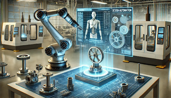
In industrial automation, CAD is used to design robotic arms, conveyor systems, and automated machinery. Engineers can simulate robotic movements and optimize assembly line configurations using CAD software, leading to improved efficiency and reduced operational costs. The integration of CAD with virtual and augmented reality further enhances design visualization, enabling engineers to interact with digital prototypes in an immersive environment.

Reverse engineering is another significant application of CAD in mechanical engineering. Engineers use 3D scanning technology to capture the geometry of existing components and create CAD models for analysis, modification, or reproduction. This approach is widely used in industries where legacy parts need to be redesigned or improved without access to original design data.

The implementation of CAD has also improved documentation and standardization in mechanical engineering. Detailed CAD models and drawings ensure that designs comply with industry standards and regulations. Furthermore, CAD facilitates digital storage and retrieval of design data, reducing the reliance on physical documents and enabling easy sharing of information across teams and organizations.

With the advent of cloud-based CAD solutions, engineers can now access their designs from anywhere, collaborate in real-time, and leverage computing power for complex simulations. Cloud-based CAD tools reduce the need for high-end hardware and offer scalable solutions for startups and small businesses. Additionally, artificial intelligence (AI) is being integrated into CAD software, enabling automated design suggestions, error detection, and predictive maintenance of mechanical systems.

Despite its numerous advantages, CAD in mechanical engineering requires skilled professionals who understand design principles, material properties, and manufacturing processes. Engineers must be proficient in using CAD software and interpreting simulation results to make informed design decisions. Many universities and technical institutes now offer specialized courses in CAD, ensuring that future engineers are well-equipped with the necessary skills.

The evolution of CAD continues with the incorporation of emerging technologies such as digital twins, where virtual models of mechanical systems are continuously updated with real-world data. This approach enhances predictive maintenance, reduces downtime, and improves system performance. The future of CAD in mechanical engineering will likely see further advancements in automation, generative design, and integration with artificial intelligence, making the design process even more efficient and innovative.

In conclusion, CAD has transformed mechanical engineering by enabling precise design, efficient analysis, and seamless manufacturing integration. From simple mechanical parts to complex systems, CAD plays a crucial role in optimizing performance, reducing costs, and accelerating innovation. As technology advances, the capabilities of CAD will continue to expand, shaping the future of engineering and manufacturing.


 Heat transfer is a fundamental discipline in mechanical engineering that deals with the movement of thermal energy between physical systems. It is crucial in various engineering applications, including power generation, HVAC systems, automotive engines, and electronic cooling. There are three primary modes of heat transfer:

  1. Conduction – The transfer of heat through a solid material or between objects in direct contact. It follows Fourier’s Law, where the heat transfer rate depends on the material’s thermal conductivity, temperature gradient, and thickness. Metals, such as copper and aluminum, have high thermal conductivity, making them efficient heat conductors.

  2. Convection – The heat transfer between a solid surface and a moving fluid (liquid or gas). It occurs in two forms:

    • Natural convection, driven by buoyancy forces due to temperature differences (e.g., air rising above a hot surface).
    • Forced convection, where an external force (fans, pumps) enhances heat transfer, commonly used in radiators and heat exchangers. Newton’s Law of Cooling governs convective heat transfer.
  3. Radiation – The transfer of heat via electromagnetic waves, independent of a medium. It follows Stefan-Boltzmann Law, where all objects emit radiation proportional to their temperature. Radiation is significant in high-temperature applications like combustion chambers and solar energy systems.

Applications of Heat Transfer

  • Cooling Systems: Heat sinks, radiators, and electronic cooling devices manage excessive heat.
  • Power Plants: Boilers, condensers, and turbines rely on heat transfer principles.
  • Heat Exchangers: Used in refrigeration, air conditioning, and chemical processing industries.
  • Aerospace & Automotive: Thermal insulation, exhaust systems, and engine cooling mechanisms.
Social Media Links:

Wednesday, 29 January 2025


 Kinematic analysis is a fundamental aspect of mechanical engineering that focuses on the motion of mechanisms and mechanical systems without considering the forces causing the motion. It plays a crucial role in designing and optimizing machines, robotics, and mechanical linkages.

Key Aspects of Kinematic Analysis

  1. Types of Motion:

    • Translational Motion: Linear movement of a body along a straight or curved path.
    • Rotational Motion: Angular movement around a fixed axis.
    • General Plane Motion: A combination of translational and rotational motion.
  2. Degrees of Freedom (DOF):

    • Defines the number of independent parameters required to describe a system's motion.
    • Governed by the Gruebler’s equation for planar mechanisms.
  3. Kinematic Chains and Mechanisms:

    • Kinematic Chain: An assembly of links and joints.
    • Mechanism: A kinematic chain with at least one fixed link used to transfer motion.
    • Common mechanisms include four-bar linkages, crank-slider mechanisms, and gear trains.
  4. Kinematic Equations:

    • Position, velocity, and acceleration analysis using mathematical equations.
    • Velocity analysis using instantaneous centers of velocity (ICV) or relative velocity method.
    • Acceleration analysis using Coriolis acceleration and angular acceleration relations.
  5. Applications:

    • Robotics and automation (e.g., robotic arms, humanoid robots).
    • Automotive (e.g., suspension systems, steering mechanisms).
    • Industrial machinery (e.g., cam mechanisms, conveyor systems).

With advancements in computer-aided engineering (CAE), kinematic analysis is now performed using simulation tools like MATLAB, SolidWorks Motion, and ADAMS, enabling engineers to optimize designs efficiently. 


Social Media Links: 


Design Automation: Enhancing Efficiency and Innovation

Design automation is revolutionizing industries by streamlining workflows, reducing human intervention, and enhancing efficiency in engineering, architecture, and product development. By leveraging artificial intelligence (AI), machine learning (ML), and computational design, design automation enables rapid prototyping, error reduction, and cost optimization. Industries such as automotive, aerospace, electronics, and construction benefit significantly from automated design tools, which integrate advanced algorithms to generate optimized solutions based on predefined constraints.

In engineering and manufacturing, design automation plays a crucial role in parametric modeling, generative design, and computer-aided design (CAD) systems. These technologies allow engineers to create adaptable models that automatically adjust to changes in specifications, minimizing manual rework. Furthermore, AI-driven design optimization enhances performance by evaluating multiple design iterations and selecting the most efficient configurations. In electronics, automation accelerates printed circuit board (PCB) layout, chip design, and system-on-chip (SoC) development, significantly reducing time-to-market.

In the construction industry, Building Information Modeling (BIM) and algorithmic design facilitate complex architectural structures, ensuring sustainability and cost-effectiveness. Generative design, powered by AI, enables architects to explore thousands of design alternatives based on material constraints, energy efficiency, and structural integrity. Additionally, robotic process automation (RPA) is integrated into construction workflows to automate repetitive tasks, improving productivity.

As industries embrace Industry 4.0, design automation continues to evolve with the integration of digital twins, cloud computing, and real-time data analytics. These advancements lead to smarter, more efficient design processes, fostering innovation while minimizing resource consumption. By automating design tasks, organizations can focus on creativity, innovation, and strategic decision-making, driving competitive advantages in a rapidly evolving technological landscape.


Tuesday, 28 January 2025


 Motion simulation in Computer-Aided Design (CAD) involves using software tools to analyze and visualize the dynamic behavior of mechanical systems and components under real-world conditions. It allows engineers and designers to predict the motion, forces, and interactions of parts in assemblies before physical prototypes are built, significantly reducing development time and costs.

The process begins with creating a detailed CAD model of the system, including all components, joints, constraints, and materials. Using simulation software, such as SolidWorks Motion, CATIA, or Autodesk Inventor, designers can input specific motion parameters like speed, acceleration, and applied forces. The simulation then calculates the resulting motion paths, velocities, and contact forces, producing results that closely mimic real-world behavior.

One of the critical applications of motion simulation is in testing the kinematics and dynamics of assemblies. For example, it helps verify the efficiency of gear mechanisms, optimize camshaft profiles, or analyze robotic arm movements. This allows engineers to identify issues like interference, excessive stress, or improper alignment early in the design process.

Motion simulation also integrates with Finite Element Analysis (FEA) and Computational Fluid Dynamics (CFD) to assess structural deformation, fatigue, and thermal effects under dynamic conditions. This holistic approach ensures designs meet performance, safety, and durability requirements.

Additionally, motion simulation enhances the design workflow by providing visual feedback through animations and graphical outputs. This aids in communicating ideas to stakeholders and improving the overall understanding of system behavior.

Applications of Motion Simulation in CAD

Motion simulation in CAD has broad applications across various industries, helping engineers optimize designs, improve performance, and reduce costs. Some of the key areas where motion simulation is applied include:

  1. Mechanical Systems Design
    Motion simulation is extensively used to design and optimize mechanical systems such as gears, cams, linkages, and mechanisms. It helps ensure that moving parts interact smoothly and efficiently, preventing interference and minimizing wear.

  2. Robotics
    In robotics, motion simulation helps optimize the movement of robotic arms, grippers, and end-effectors. Engineers can test and refine the kinematics and dynamics of robots before physical prototypes are built. This is crucial for applications in manufacturing, assembly, and medical robotics, where precision and reliability are critical.

  3. Automotive Engineering
    Automotive manufacturers use motion simulation to test the movement of components like suspension systems, steering mechanisms, and door latches. This allows designers to assess vehicle performance, optimize comfort, and ensure safety under dynamic conditions, reducing the need for physical testing.

  4. Aerospace and Aviation
    In aerospace engineering, motion simulation plays a crucial role in designing landing gear, flight control systems, and other critical components. By simulating the motion under different flight conditions, engineers can enhance the safety, stability, and performance of aircraft and spacecraft.

  5. Consumer Products
    Motion simulation is used in the design of everyday products such as kitchen appliances, toys, and furniture. It helps improve the functionality of moving parts like hinges, sliders, and locks, ensuring ease of use and durability.

social Media Links:

Sunday, 26 January 2025


 Static and Dynamic Analysis are fundamental tools in mechanical engineering used to evaluate the behavior of structures and mechanical systems under various loads. These analyses ensure that designs are safe, efficient, and reliable in different operational conditions.

Static Analysis

Static analysis focuses on the response of a structure or system to constant, time-invariant loads. These loads include forces such as weight, pressure, or thermal stresses that remain unchanged over time. The primary goal is to determine the stress, strain, and deformation of the object under these static loads.

For example, in bridge design, engineers use static analysis to calculate the stress distribution when vehicles are stationary. It identifies weak points, ensuring the structure can handle the applied loads without exceeding material strength or causing excessive deformation.

Key aspects of static analysis:

  • Stress and strain evaluation.
  • Calculation of safety factors.
  • Determination of deformation and displacement.
  • Assessment of load-bearing capacity.

Dynamic Analysis

Dynamic analysis, on the other hand, deals with structures subjected to time-varying or fluctuating loads. These loads can include forces from vibrations, impacts, or oscillations. Unlike static analysis, dynamic analysis considers inertia and damping effects, as the system's response changes with time.

For example, in automotive engineering, dynamic analysis is used to study how a car chassis reacts to road-induced vibrations or during collisions. This ensures the vehicle performs reliably under dynamic conditions.

Key aspects of dynamic analysis:

  • Study of vibrations, natural frequencies, and mode shapes.
  • Analysis of transient responses to time-dependent forces.
  • Fatigue analysis due to repetitive loading.
  • Consideration of damping and energy dissipation.

Importance

Both analyses play a vital role in engineering design. Static analysis ensures stability under steady conditions, while dynamic analysis ensures performance under real-world scenarios involving motion or time-varying forces. Together, they enable engineers to create robust, durable, and efficient systems in fields such as aerospace, automotive, civil engineering, and manufacturing.


Applications of Static Analysis

Static analysis is used to evaluate systems under constant loads and ensures their stability and strength. It is applied in:

  1. Civil Engineering:

    • Design of bridges, buildings, and dams to ensure they can withstand permanent loads such as weight and external forces.
    • Foundation analysis to determine bearing capacities and settlement predictions.
  2. Mechanical Engineering:

    • Structural design of machinery components like beams, shafts, and gears under constant loading.
    • Stress analysis of static equipment such as pressure vessels, storage tanks, and pipes.
  3. Aerospace Engineering:

    • Analysis of airframes and wings under steady aerodynamic forces during flight.
    • Evaluation of landing gear systems under static loads during aircraft parking.
  4. Automotive Engineering:

    • Stress analysis of chassis and frames under static loads like engine weight.
    • Assessment of suspension systems under stationary vehicle conditions.
  5. Renewable Energy:

    • Structural integrity checks of wind turbine towers and solar panel mounting systems under steady environmental forces.

Applications of Dynamic Analysis

Dynamic analysis is essential for systems subjected to time-dependent or fluctuating forces. It is applied in:

  1. Automotive Engineering:

    • Vibration analysis of engines and drivetrains to minimize noise and improve performance.
    • Crash simulations to study impact forces and energy dissipation in vehicle safety systems.
  2. Civil Engineering:

    • Seismic analysis of buildings and bridges to evaluate their performance during earthquakes.
    • Wind-induced vibration studies for tall structures like skyscrapers and communication towers.
  3. Aerospace Engineering:

    • Modal analysis of aircraft components to prevent resonance during operation.
    • Flutter and vibration studies of wings and control surfaces.
  4. Mechanical Engineering:

    • Analysis of rotating machinery like turbines and compressors to prevent fatigue and failure.
    • Study of dynamic loads in robotic arms and automation equipment.
  5. Renewable Energy:

    • Evaluation of wind turbine blades under dynamic wind loads to ensure reliability.
    • Analysis of wave energy converters subjected to fluctuating ocean forces.
  6. Marine Engineering:

    • Ship structure analysis to assess responses to wave-induced vibrations.
    • Study of propeller-induced oscillations on hulls.
Social Media Links:

Leveraging Predictive AI in Telecommunications with RAN Intelligent Controller (RIC)

  In the dynamic landscape of telecommunications, the RAN Intelligent Controller (RIC) has emerged as a transformative technology. The trans...