Monday, 26 June 2023

CAD for ship and marine engineering 


more information:
Computer-Aided Design (CAD) plays a crucial role in ship and marine engineering, enabling engineers to design and develop various components and systems used in the maritime industry. CAD software allows for precise and efficient modeling, simulation, and analysis of ships, marine structures, and related systems. Here are some key areas where CAD is commonly utilized in ship and marine engineering:
Ship Design: CAD software enables naval architects and marine engineers to create detailed 2D and 3D models of ships and vessels. They can design hulls, superstructures, decks, compartments, and other structural elements, taking into account hydrodynamics, stability, and regulatory requirements.
Structural Analysis: CAD tools assist in analyzing the structural integrity and strength of ship components and marine structures. Engineers can simulate various loads, such as waves, wind, and cargo, to evaluate stresses, deflections, and deformations. Finite Element Analysis (FEA) is often used to determine the structural response under different conditions.
Piping and HVAC Systems: CAD software allows for the design and routing of complex piping systems onboard ships. Engineers can create detailed diagrams, specify pipe dimensions, and analyze flow characteristics. Similarly, HVAC (Heating, Ventilation, and Air Conditioning) systems can be designed and optimized using CAD tools to ensure efficient climate control within the vessel.
Electrical and Control Systems: CAD facilitates the design of electrical distribution networks, control panels, and instrumentation systems for ships. Engineers can create wiring diagrams, cable schedules, and equipment layouts. Integration with electrical simulation tools helps analyze and optimize the performance of electrical systems.
Propulsion and Power Systems: CAD aids in designing propulsion systems, including engines, propellers, and thrusters. It allows engineers to model and simulate the interaction between the ship's hull and propulsion components to optimize performance and efficiency. Additionally, CAD can be used to design power generation and distribution systems for onboard electrical needs.
Ship Interior and Accommodation: CAD tools are used to design and plan ship interiors, including cabins, common areas, galleys, and crew facilities. Architects can create realistic 3D visualizations, enabling stakeholders to review and modify interior layouts before construction.
Production and Manufacturing: CAD models are essential for translating design concepts into actual ship components. Shipyards and manufacturers use these models for manufacturing planning, creating production drawings, and generating CNC (Computer Numerical Control) machine instructions. This improves accuracy and efficiency in the manufacturing process.
Overall, CAD plays a vital role in ship and marine engineering, assisting in the design, analysis, and production of ships, marine structures, and their associated systems. It enables engineers to visualize and optimize designs, ensuring safety, performance, and compliance with industry standards

Product Design Prototyping in CAD 

more information:
Product design prototyping is an important step in the development of any product. There are lots of stories and studies sharing the value of this, but suffice it to say, without prototyping, product development would be much more time consuming, expensive, and risky.
Prototyping, in its most formal definition, is the production of a functional product, built in materials as close as possible to the production materials, built to the tolerances of the production drawings and assembled to test. These prototypes we call “Engineering Check Prototypes” because they “check” our engineering and are used for full functional testing. Sometimes these can also be used in Compliance Testing and Certification submission for UL, FCC, TUV, CE, CSA and others. There is a caveat here about certain submissions requiring full production molded parts, not machined samples in the same materials, although it seems to be a case by case issue depending on the product and/or market.
Prototyping, more broadly interpreted, can and is used for validation in many steps of the development process. It can be used as form studies to check ergonomics, subsystem test builds to assure function early in the process or engineering check prototypes to check engineering files and test prior to production ramp up.
Prototyping described above is really just prototyping of products, but product design prototyping could also apply to computer software applications or web site apps. These digital products are often prototyped to test user interactions and market acceptance. Google developed a process called “Design Sprints” which is an accelerated process to study and identify problems, conceptualize and develop solutions, create prototypes and test them in about 5 days. Obviously, because it started with apps, the prototyping can be done very quickly (in hours not weeks) and testing can be done on a phone, tablet or desktop from those visual page examples.
The development process starts with proving the idea works, leads to physical studies of the device, mechanical and any other engineering occurs for production of the device and testing, tooling and ramp up begins. We’ll share how product design prototyping applies at each step of the development process as it flows from initial concept to mass production.
vbisit: https://cad-conferences.sciencefather.com/


computer aided design engine


#news: computer aided design engine
more information:
CAD communication tools have evolved over the past 60+ years. At Design-engine we call CAD communication tools. From 2D line drawings to 3D CAD tools and in turn, these always placed a demand on the speed and innovation of the computers that operate them. Mainframe first followed by Unix based processors and Windows NT circa 1993 before moving on to Dell Precision mobile workstations.
In the 1960s, large Automotive and Aerospace companies began to develop their own proprietary CAD/CAM systems for internal use. Yamaha had developed a home grown system for product development, as well as Boeing & HP, because there was nothing on the market. IBM even had a parametric sheet metal package in 1985-86 before PTC but they never took to market. Only the most progressive companies had access to computer aided design. It was debatable whether CAD was more productive than traditional techniques as it was all 2-dimensional. Changes to the drawing were so key because the final output was so clean. CATIA started as an in-house development by French aircraft manufacturer, Avions Marcel Dassalt(AMD). That software helped to develop Dassault’s Mirage fighter jet.

Monday, 12 June 2023


 CAD for microelectromechanical systems (MEMS)

#news: CAD for microelectromechanical systems (MEMS)
more information:
Computer-Aided Design (CAD) plays a crucial role in the design and development of microelectromechanical systems (MEMS). MEMS are miniaturized devices that integrate mechanical elements, sensors, actuators, and electronics on a single chip. CAD software tools specifically designed for MEMS enable engineers to model, simulate, and optimize these complex systems efficiently.
Here are some key aspects of CAD for MEMS:
2D/3D Modeling: CAD software provides a platform to create accurate geometric models of MEMS devices. Engineers can design various components, such as microstructures, electrodes, and interconnects, using intuitive 2D and 3D modeling interfaces.
Parametric Design: CAD tools allow engineers to define and modify design parameters of MEMS devices easily. By employing parametric modeling techniques, designers can explore different design alternatives and optimize device performance.
Simulation and Analysis: MEMS CAD software provides simulation capabilities to predict the behavior of devices under different operating conditions. Engineers can simulate the mechanical, electrical, thermal, and fluidic aspects of MEMS to evaluate their performance, reliability, and manufacturability.
Structural Analysis: Finite Element Analysis (FEA) helps assess the structural integrity, stress distribution, and deformation of MEMS components.
Electrostatic Analysis: CAD tools simulate the electrostatic forces and capacitance effects in MEMS devices, which are crucial for devices like accelerometers and gyroscopes.
Thermal Analysis: CAD software enables engineers to analyze heat dissipation, thermal stress, and temperature distribution in MEMS devices.
Fluidic Analysis: For MEMS devices involving fluid flow, Computational Fluid Dynamics (CFD) simulations assist in analyzing fluid behavior and optimizing designs.
Design Optimization: CAD software incorporates optimization algorithms that enable engineers to improve MEMS device performance, such as sensitivity, response time, and power consumption. Optimization techniques, such as genetic algorithms or gradient-based methods, can be applied to find optimal design parameters.
Process Integration: MEMS CAD tools often provide process design kits (PDKs) that include process-specific information, material properties, and design rules. This information allows designers to align their models with the capabilities and constraints of the MEMS fabrication processes, ensuring manufacturability.
Layout and Mask Generation: CAD software assists in generating layout files and masks required for MEMS fabrication. The software can convert the design models into the appropriate file formats compatible with fabrication equipment
#MEMS:#Engineering#CAD#Microfabrication #Microengineering
visit : https://cad-conferences.sciencefather.com/
CAD software TopSolid'Design - computer aided design

#news: CAD software TopSolid'Design - computer aided design -
more information:
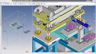
TopSolid'Design is a computer-aided design (CAD) software developed by Missler Software. It is a comprehensive 3D CAD solution that offers a wide range of tools for designing and modeling various objects and products. TopSolid'Design is known for its powerful parametric modeling capabilities and its user-friendly interface.
Here are some key features of TopSolid'Design:
Parametric Modeling: TopSolid'Design allows you to create 3D models using parametric techniques. This means that you can define relationships between different parts of your design, allowing for easy modification and updates.
Assembly Design: The software provides advanced assembly design capabilities, allowing you to create complex assemblies of parts and components. You can manage the relationships between different parts, check for interferences, and simulate the motion of assemblies.
Sheet Metal Design: TopSolid'Design includes dedicated tools for designing sheet metal parts. You can create sheet metal components, unfold them to generate flat patterns, and specify bend allowances and corner reliefs.
Drafting and Documentation: The software offers comprehensive drafting features, enabling you to create detailed 2D drawings from your 3D models. You can add dimensions, annotations, and other annotations to create professional documentation.
Surface Modeling: TopSolid'Design supports advanced surface modeling capabilities, allowing you to create complex and organic shapes. You can create smooth surfaces, fillets, and blends to achieve the desired aesthetic and functional properties.
Collaboration and Integration: The software supports collaboration and data exchange with other CAD systems through various formats like STEP, IGES, and DXF. It also integrates with other modules of the TopSolid suite, such as TopSolid'Cam for computer-aided manufacturing (CAM).
Simulation and Analysis: TopSolid'Design includes simulation features that allow you to validate your designs before manufacturing. You can perform collision detection, interference checking, and kinematic simulations to ensure that your designs are functional and error-free.
Overall, TopSolid'Design is a powerful CAD software solution that provides a comprehensive set of tools for designing and modeling. It is widely used in various industries, including mechanical engineering, automotive, aerospace, and more
#CAD#3DDesign#Engineering#Manufacturing#ProductDesign
visit:https://cad-conferences.sciencefather.com/

Leveraging Predictive AI in Telecommunications with RAN Intelligent Controller (RIC)

  In the dynamic landscape of telecommunications, the RAN Intelligent Controller (RIC) has emerged as a transformative technology. The trans...