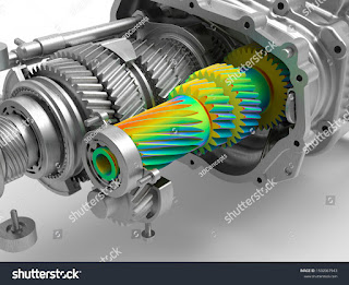
Finite Element Analysis
#news: Finite Element Analysis
more information:
Finite Element Analysis (FEA) is a computational technique used to analyze and solve complex engineering problems. It is based on the concept of dividing a complex structure or system into smaller, finite elements and solving mathematical equations to approximate the behavior of the overall system.
Here's a step-by-step overview of the finite element analysis process:
Preprocessing: The first step involves defining the problem and creating a finite element model. This includes selecting the geometry, material properties, and boundary conditions of the system. The geometry is typically divided into a mesh of smaller elements, such as triangles or quadrilaterals in 2D or tetrahedra or hexahedra in 3D.
Formulation: In this step, the governing equations that describe the behavior of the system are derived. These equations can be based on principles of solid mechanics, fluid mechanics, heat transfer, electromagnetics, or other physics depending on the problem being analyzed.
Discretization: The continuous equations obtained in the previous step are discretized by applying approximation methods such as the finite element method. Each element in the mesh is associated with a set of shape functions that define how the variable of interest (e.g., displacement, temperature) varies within the element.
Assembly: The discrete equations for each element are combined to form a global system of equations that represents the behavior of the entire structure or system. This involves assembling the element stiffness matrices, load vectors, and boundary conditions into a system matrix and a system vector.
Solution: The system of equations obtained in the previous step is solved numerically to obtain the unknown values of the variables of interest. Various solution techniques can be used, such as direct methods (e.g., Gaussian elimination) or iterative methods (e.g., conjugate gradient method).
Postprocessing: Once the solution is obtained, the results can be visualized and analyzed. This includes generating contour plots, stress distribution plots, displacement plots, or any other relevant output to understand the behavior of the system under different conditions.
Finite Element Analysis is widely used in various engineering disciplines, including structural analysis, fluid dynamics, heat transfer, electromagnetic analysis, and many others. It allows engineers to simulate and predict the behavior of complex systems before physically building them, enabling optimization, design validation, and cost reduction.
Types of Elements: In FEA, there are different types of elements used to discretize the geometry, such as linear elements (e.g., triangles, tetrahedra) and higher-order elements (e.g., quadratic or cubic elements). The choice of element type depends on the complexity of the problem and the desired accuracy of the analysis.
Material Properties: FEA requires the definition of material properties, such as elasticity, density, thermal conductivity, and more, depending on the type of analysis. These properties dictate how the material behaves under different loading and environmental conditions.
Boundary Conditions: Boundary conditions are essential for defining the behavior of the structure or system being analyzed. They include constraints, such as fixed supports, prescribed displacements, applied forces or pressures, and thermal conditions. These conditions help simulate real-world scenarios and determine the response of the system.
Static and Dynamic Analysis: FEA can be used for static analysis, which involves determining the equilibrium state of a structure under applied loads. It can also handle dynamic analysis, which considers the time-dependent behavior, such as natural frequencies, mode shapes, and response to transient or harmonic excitations.
Nonlinear Analysis: FEA can handle nonlinear problems, where material properties, boundary conditions, or geometry exhibit nonlinear behavior. This includes material nonlinearity (plasticity, hyperelasticity), geometric nonlinearity (large deformations), and contact/nonlinear friction effects.
Meshing: Mesh generation is a critical step in FEA, where the geometry is divided into smaller elements. The quality of the mesh, such as element shape, size, and density, affects the accuracy and convergence of the analysis. Automatic and manual meshing techniques are available, and considerations must be made for capturing regions of interest or high-stress concentrations.
Convergence and Accuracy: FEA is an iterative process, and convergence criteria are used to assess the accuracy of the solution. Convergence is achieved when the solution reaches a stable and consistent state, typically by satisfying certain error tolerances or equilibrium conditions.
Postprocessing Tools: FEA software provides various postprocessing tools to visualize and interpret the results. These tools allow engineers to examine stress and strain distributions, displacements, deformation contours, temperature profiles, and other quantities of interest.
Verification and Validation: It is crucial to verify and validate FEA models to ensure their accuracy and reliability. Verification involves comparing the results with known analytical or experimental solutions, while validation entails comparing FEA predictions with real-world data or measurements.
Applications: FEA has a broad range of applications, including structural analysis (e.g., buildings, bridges, aerospace structures), mechanical systems (e.g., automotive components, machinery), fluid dynamics (e.g., flow simulations, aerodynamics), thermal analysis (e.g., heat transfer, thermal stress), electromagnetic analysis (e.g., electrical machines, antennas), and more.
Finite Element Analysis is a powerful tool for engineers and scientists, allowing them to gain insights into complex systems and make informed design decisions. The method's versatility and wide range of applications contribute to its popularity in various industri
visit:https://cad-conferences.sciencefather.com/


